Posts

Showing posts from 2018

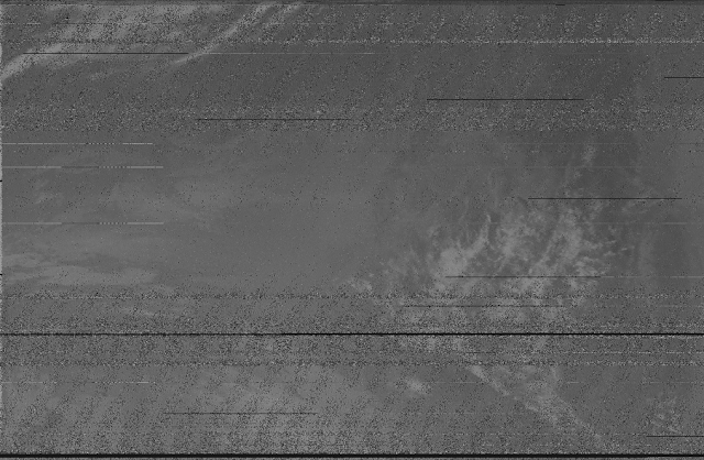
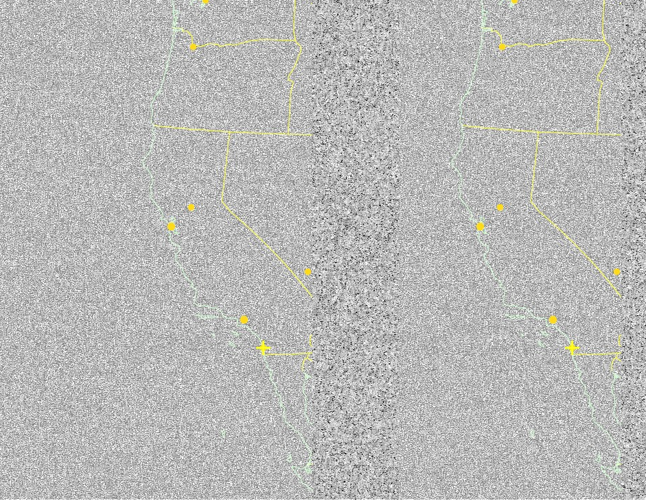
RTL-SDR NOAA satellite Images

Image
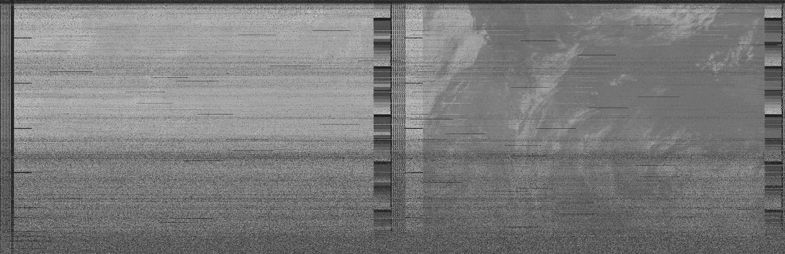
Turns out most of my other images were actually images produced from signals that were not NOAA signals, whoops. Here are some images I managed to get here at Caltech. Our good friends at the local NPR station (KPCC 89.3) over at Pasadena Community College as well as all the other radio noise here are not helping the quality of the images. I need to frequently adjust the antenna orientation to try and block out the differently polarized signals and to only get the circularly polarized satelite signal. I'm using a QFH tuned (very roughly tuned) to 137 MHz.

Amature Radio with an RTL-SDR 2

Image
This is part 2 to my adventure into amature radio receiving. I conveyed my intention to receive images from NOAA satellites in the first part. I was unable to replicate the results of the possible image, despite the construction of a 137 MHz V-dipole antenna (albeit probably not the best antenna since I am not experienced in antenna construction). Tomorrow I'll try building the antenna detailed here . Hopefully that will give me sufficient signal intensity to receive visually recognizable images. The other complicating factor is I'm uncertain how to match the default 11.250kHz sampling of the audio input file in wxtoimg with the 44.1kHz sampling of audio by CubicSDR and then the 44.1kHz sampling of the recording program. I did change the wxtoimg sampling to 44.1kHz however any potential image was distorted beyond the ability of wxtoimg to overlay a map upon it. I'll update you tomorrow (I guess whenever I say tomorrow in this post I mean today since it's past midnight)

Microstate table for a d3 electronic configuration.

This was just a test to see if I could put LaTeX formatted tables into this webpage MathJax example $$\begin{array}{|c | c | c | c | c|} \hline \begin{array}{c}\end{array} & \frac{3}{2} & \frac{1}{2} & -\frac{1}{2} & -\frac{3}{2} \\ \hline 5 & \begin{array}{c}\end{array} & ^{2}H\begin{array}{c}^{2}H(2^+,2^-,1^+)\end{array} & \begin{array}{c}(1^-,2^-,2^+)\end{array} & \begin{array}{c}\end{array} \\ \hline 4 & \begin{array}{c}\end{array} & ^{2}G\begin{array}{c}^{2}H(2^+,2^-,0^+)\\^{2}G(2^+,1^+,1^-)\end{array} & \begin{array}{c}(0^-,2^-,2^+)\\(1^-,2^-,1^+)\end{array} & \begin{array}{c}\end{array} \\ \hline 3 & ^{4}F\begin{array}{c}^{4}F(2^+,1^+,0^+)\end{array} & ^{2}F\begin{array}{c}^{2}H(2^+,2^-,-1^+)\\^{2}G(2^+,1^+,0^-)\\^{4}F(2^+,1^-,0^+)\\^{2}F(2^-,1^+,0^+)\end{array} & \begin{array}{c}(1^-,2^-,0^+)\\(0^-,2^-,1^+)\\(0^-,1^-,2^+)\\(-1^-,2^-,2^+)\end{array} & \begin{array}{c}(0^-

Amature Radio Using an RTL-SDR

Image
     I recently began exploring the world of amateur radio by purchasing a software-defined radio (sdr) which allows one to view a wide band spectrum of radio frequencies (RF). Mine goes from 70 MHz to about 2300 MHz. Although this is just shy of being able to see wifi, there is an sdr that has this capability for about 20 times the cost (HackRF One) and is for the time being far too costly given the general uncertainty involved with sdr.      The uncertainty I'm referring to is what happens when you ask for an inexpensive device that can detect a range as wide as 100KHz-6GHz (I think this is the hackrf one range). This is an extremely tall order. In fact most radio devices have rapidly degrading specs when pushed outside of the range they were designed to operate within. I can think of two good reasons for this, the first being cost, it is more cost effective to fabricate a chip designed to operate at a narrow frequency band rather than having wideband capable devices and only